I bought some rotary encoders to interface with an Arduino. There are examples of code that can be used to read the encoder in a variety of websites. The one I tried was a little glitchy, but it may be due to not doing any filtering of the switch outputs. So, I was going to add some caps and clean up the outputs but decided that I would rather implement the decoding function in hardware. This would simplify the code and use fewer Arduino resources.
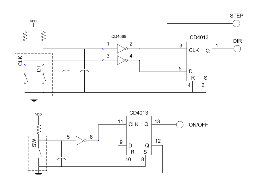
Decoding a rotary encoder is very simple with just a D-Flip Flop. One encoder switch output goes to D and the other goes to CLK. I figured that I was not the only person to arrive at this realization. Sure enough, I found a very nice writeup on an implementation using a DFF here: http://AC-DC Switching regulator uninterruptible power supply.
The addition of the Schmitt triggers is a nice touch for additional noise immunity. Not having any, I decided to build the circuit using a CD4069 hex inverter. I also wanted to incorporate the push switch feature of my rotary encoder, so my design is a little different.
During the same time I was thinking about rotary encoders, I was also pondering DIY PC boards. This was the perfect project for that. After lots of back and forth, I decided on using the hot-toner-transfer method. I ran a number of experiments to perfect the method and arrived at the following very simple methodology.
- Design the layout of the board using ExpressPCB software. Since I am using the toner-transfer method, I will just need to print the resulting layout to a PDF file (I will explain why PDF instead of direct to printer later). Moreover, I like using ExpressPCB because once I perfect the layout, I can send the design to them and get three double-sided boards for a little over $50. Since my DIY board is single sided, I laid out the board so that I use minimum of backside traces.
- Using Adobe Illustrator (AI), open the PDF file, delete the bounding box that ExpressPCB software generates. Move the layout to the top of the page, and make a number of copies of the layout and place them in various places on the page. This gives me the option to do multiple tries as my technique is perfected. I can also do multiple boards though that is not my goal. So, the reason for printing to PDF is to give the ability to edit the file in AI.
- Print the newly edited PDF file to a real printer. I have tried the HP LaserJet P1102W using LD Products toner. Not so good. Printing to my Brother MFC-7860DW copier/fax/printer generated very nice output. I printed in 1200 dpi but I don’t think it makes much difference. I printed to several types of paper (lots of ideas on paper choices can be found on the internet). I used some transfer paper I bought many many years ago and never used. It came from DynaArt Designs which is now PulsarProFX.
- Transfer the image to a PCB. Very simple. Lay the image on a perfectly clean PCB and press a hot iron over it for about three minutes–all the time applying lots of pressure. The place the board and paper into a water bath and leave it until the paper separates leaving the traces on the PCB. Takes about another two minutes.
- Etch the board using Ferric Chloride.
- When etching is complete, rinse in water. Then remove the traces using acetone.
- Done.
I have made several board. For one, I heated the Ferric Chloride with a hot plate. The etch went very fast. The second time I did not heat the fluid and the etch took longer.
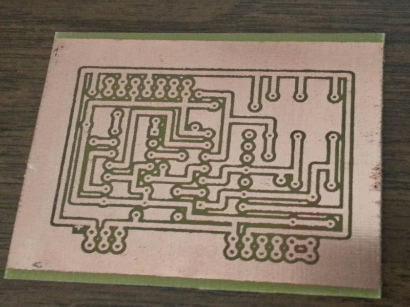
Here is the resulting PCB
It is not perfect, but not bad for very early in the learning curve! The key to successful etching is adding the flood fill so that etching can be uniform (more or less) throughout.
I populated the board as shown below
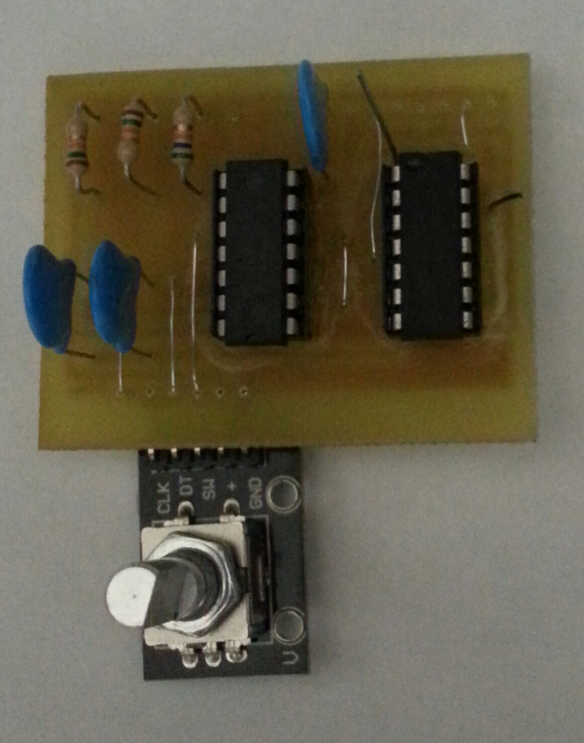
The caps are 22nF and the resistors are 15K. Not critical.
I powered it up and it worked just fine!!
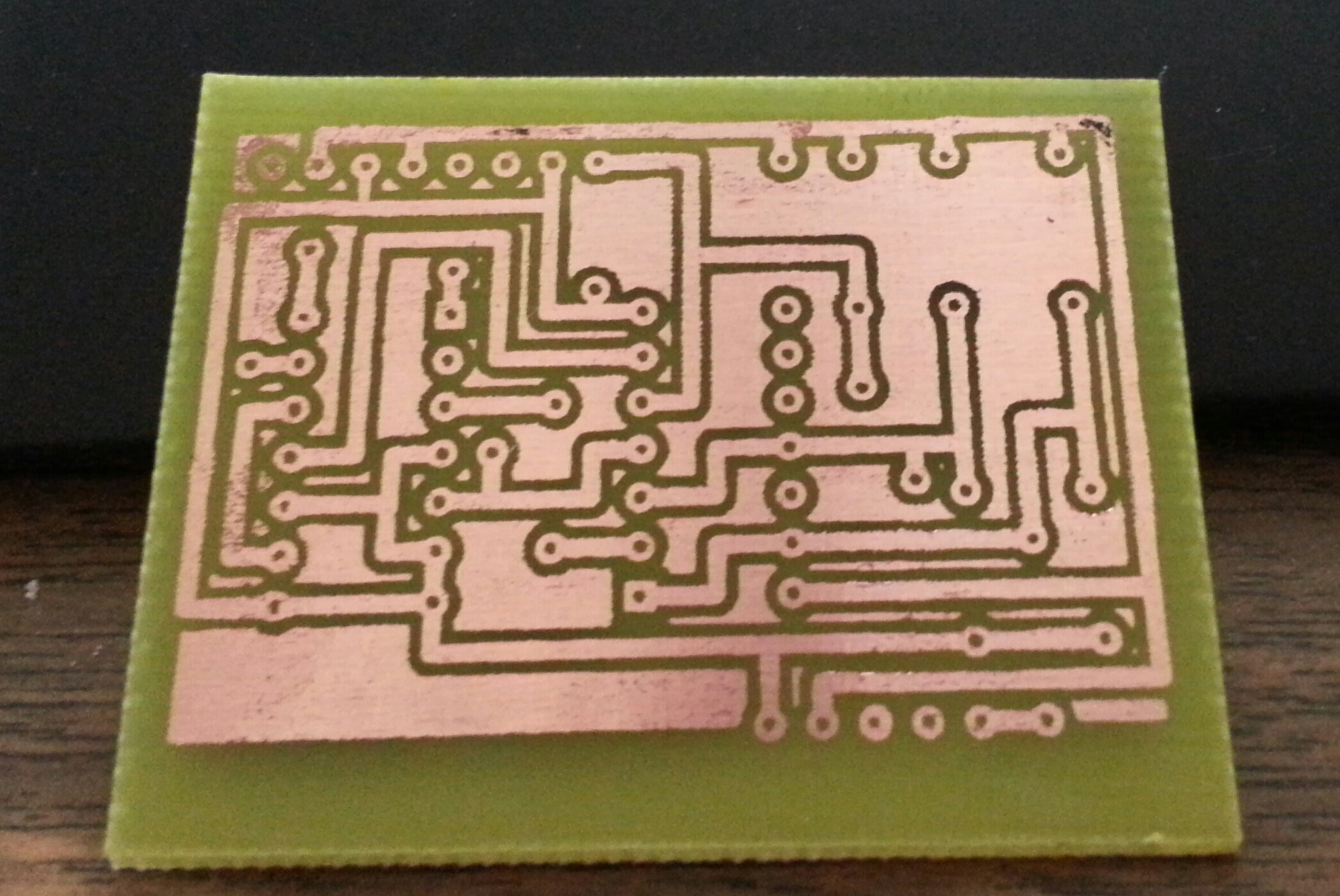
A few days later I decided to improve the layout so that I can attached the rotary encoder with a stake header. Also, I wanted another iteration of my lithography and etching technique. Here is the updated board. Quite nice.