A long time ago, IC designers would breadboard their designs prior to committing to the fab. This worked pretty well for small logic designs because MSI Logic was readily available (74xx series dominated) and the number of gates were generally manageable. We used panels of wire-wrap sockets for the designs and they were wired using wire-wrap. Wire-wrap was a 30-gauge wire with a thin Teflon coating. When wrapped tightly on a square gold-plated pin, the sharp edges of the pin cut through the Teflon coating, making a connection.
Noting is perfect. Sometimes the wrap was not tight enough to make a secure electrical contact. Sometimes, a connection was simply missed. Rather than installing the chips and troubleshooting with oscilloscopes and logic analyzers, the breadboard was first tested for continuity…every connection on the schematic was verified. This was a tedious process.
A common tool for this job was a “buzz box” or continuity checker, as it were. Rather than register a visual reading, an audible “buzz” indicated a good connection.
I had the idea for a “buzz box” back in 1981. The idea was motivated by several things. First, I did not want to have a power switch because invariably, the thing would be left on and the battery run down. Second, I wanted the ability to buzz out circuits where chips were installed. These were two interesting challenges.
The idea I am presenting here came to me one morning as I awoke–I had been pondering this day and night. I immediately sketched out the idea on a piece of paper and when I got to the office, I set about proving the concept. It worked…it was beautiful. I thought it to be so clever that I submitted it to a publication “Electronics” for an article in their “Designer’s Notebook” section. Sure enough the article was accepted and I got $50 for my trouble.
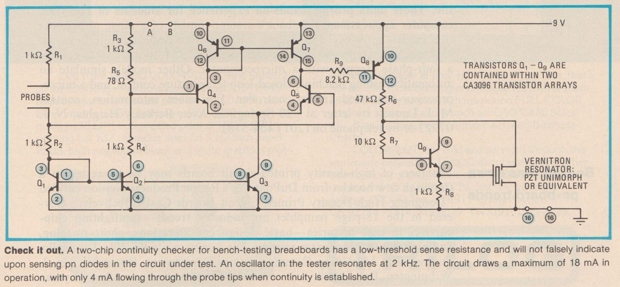
Here it is scanned from Nov 13, 1981 edition of Electronics.