Monthly Archives: January 2016

FFT of a Sampled Sine Wave

I needed some graphics illustrating the frequency spurs of the output of a DAC when converting a sine wave.  The calculations of the spur frequencies is a function of the oversampling of the sinusoid and is trivial.  But, I needed graphics.  I thought about just drawing them in MSVisio but then decided that it would be fun to let Excel do the work for me.

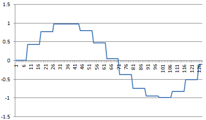
So, I wrote a Visual Basic routine in Excel that first generated a sampled-data sinusoid, then calculated the FFT of that waveform and plots both the waveform and the FFT.  The parametric inputs for the calculations are the number of data points (must be power of 2), and the over sample ratio.  Again pretty simple stuff.

Here is an example output of a sampled sinusoid:

SampleSine

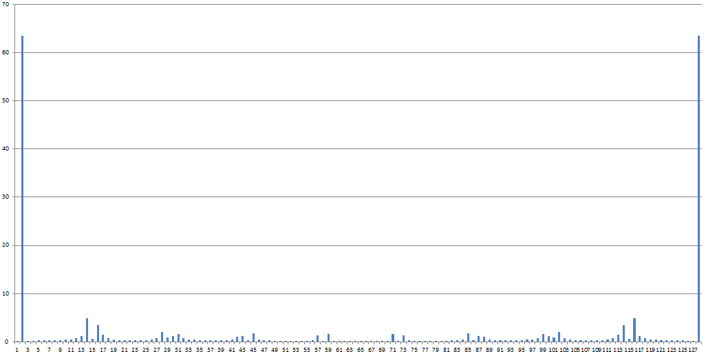
Here is the FFT output:

SampleFFT

Here is the VB code to do this:

Sub FFTDAC()
Application.Calculation = xlCalculationAutomatic
Application.EnableEvents = True
Columns(“C:C”).Select
Selection.ClearContents
Pi = 3.1415926
Range(“H1”).Offset(0, 0).Select
samples = Selection.Offset(0, 0).Value
OSR = Selection.Offset(1, 0).Value
inc = samples / OSR
Range(“A1”).Offset(0, 0).Select
For i = 1 To samples
arg = i – i Mod inc
arg = arg * 2 * Pi / samples
Value = Sin(arg)
Selection.Offset(0, 0).Value = Value
Selection.Offset(1, 0).Select
Next i
Range(“D1”).Offset(0, 0).Select
For i = 1 To samples
cellname = “C” & i
fcn = “=ImAbs(” + cellname + “)”
Selection.Offset(0, 0).Value = fcn
Selection.Offset(1, 0).Select
Next i

Application.Run “ATPVBAEN.XLAM!Fourier”, ActiveSheet.Range(“$A$1:$A$128”), _
ActiveSheet.Range(“$C$1”), False, False
End Sub

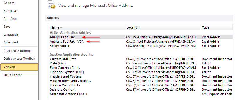
In order for this macro to work, you have to install/enable the Analysis ToolPak and Analysis ToolPak VBA

VBA setup


Hack of an iRig Pre XLR preamp with phantom power

Recently I wanted to do some recording onto a camcorder using a high-end microphone.  The camcorder had an line-in 3.5mm jack so I needed to get from the microphone having the XLR connector requiring phantom power to the 3.5mm female connector at the proper signal levels.  I tried using my Tascam 8-channel digital studio (mic in, headphone out to the camera).  Never could make it work and my patience was such that I opted for a different solution with a mic of lesser quality.  I made the recording and am happy enough for now.

Now I have purchased a new camcorder and it is on its way. I am determined to figure out how to solve the XLR problem.  As it happens, I have owned this little iRig Pre Mic converter/preamp.  It was designed to interface with Apple devices using a TSSR 3.5mm jack.  Never was happy with the performance on the Apple device, so it has been collecting dust.  So, I decided to see if there was some kind of mod I could do on it to make it useful for my intended purpose.

Thankfully, most of the work has been done for me.  I found some videos describing how to hack the 3.5mm cable so that it forces the preamp to operate and drive out to the headphone jack.  In the video hack, the guidance is to cut the cable and solder certain wires together and leave others untouched.  I really did not want to destroy the cable.  I preferred the idea of doing temporary shorts on the male TSSR jack.  To do this, I needed to figure out which wires went where.  Ohm meter to the rescue.  Here is what I resolved.

2016-01-05 14_29_37-iRig Pre Hack.pdf - Foxit ReaderSince I wanted to preserve the jack, I did not solder to it.  First I took some shrink tubing and covered the Green ring so that it is not exposed.  Then, I tightly wrapped a wire around the remaining exposed rings, spanning the length of the jack.  Then covered it with larger shrink tubing and voila!

I have since ordered two TSSR extensions.  I will cut one and short the appropriate wires.  When I want to use the hacked iRig, I just plug in the hacked extension.  Otherwise, the iRig is in default factory condition.