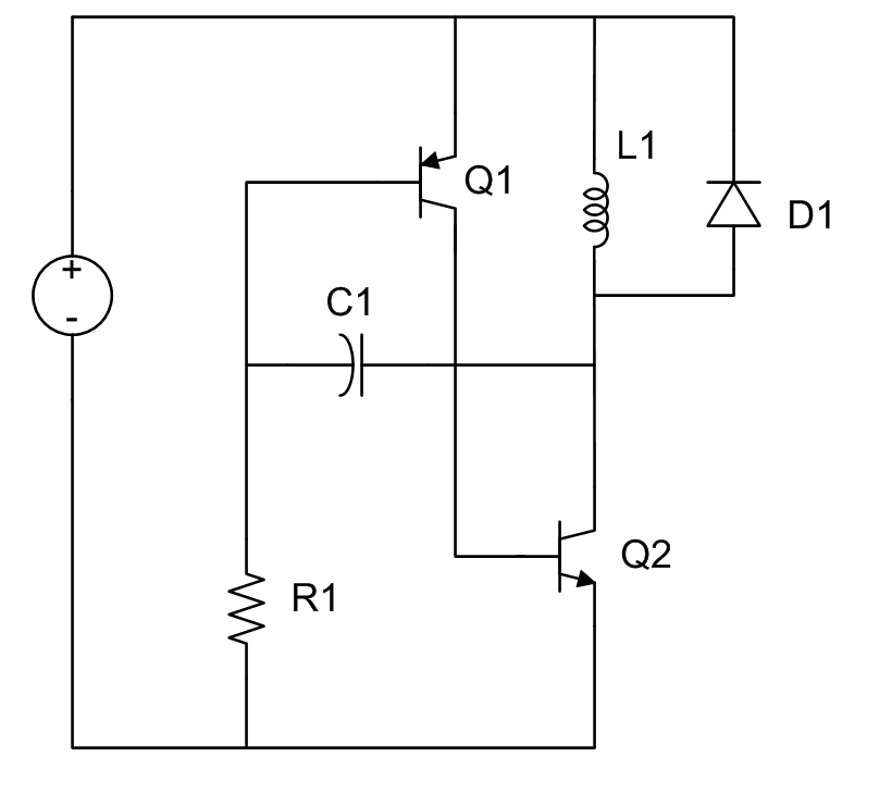
I saw this circuit on a Youtube EEVBlog video. It is an LC relaxation oscillator. I do not recall seeing a relaxation oscillator using inductors and capacitors, so naturally it piqued my interest. Here is the circuit.
The first thing I did was build the circuit in the lab and see how it performed. I used an LED for the diode.
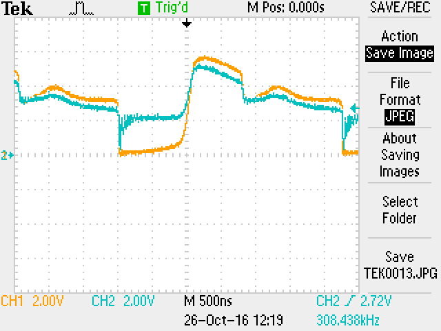
Yellow is the collector of Q2 and the blue is the base of Q1.
Very interesting waveshape. Let’s see how this circuit works.
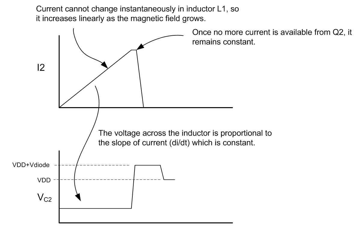
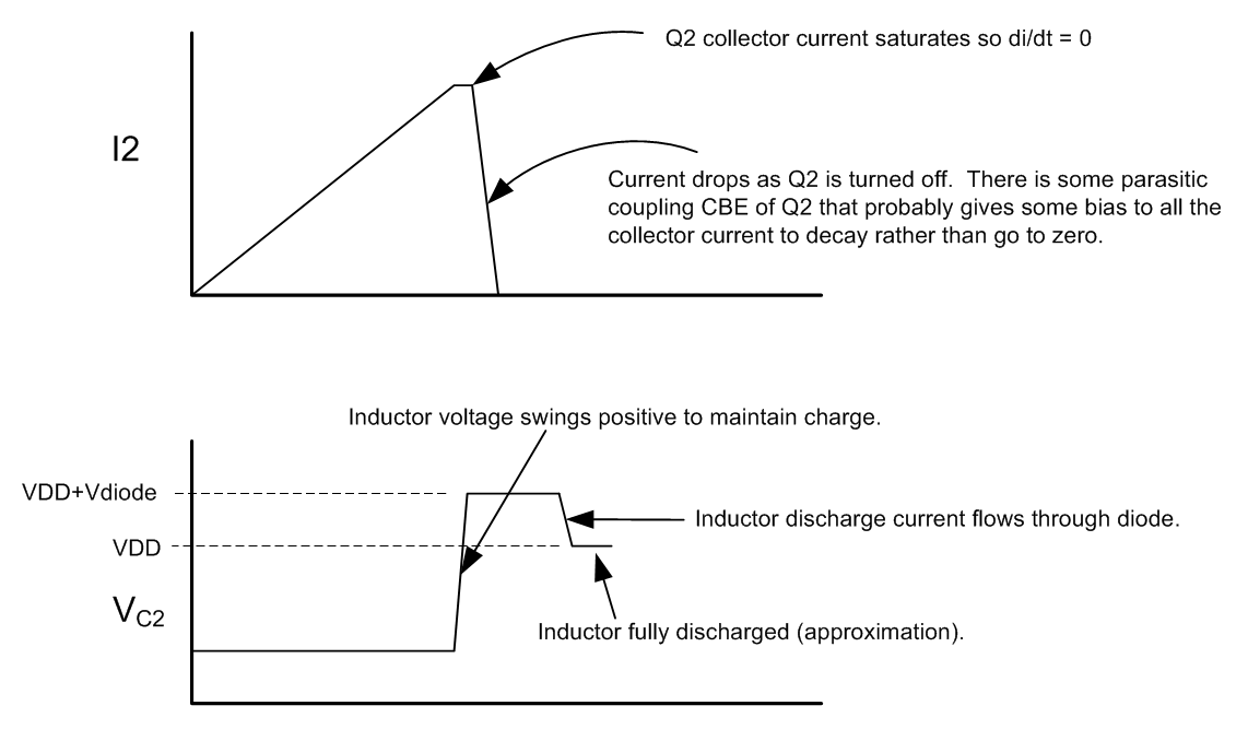
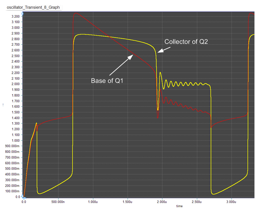
When power is applied, Q1 and Q2 turn on. Collector of Q2 pulls to ground. Since current cannot change instantaneously, the voltage applied across the inductor allows a fixed di/dt to charge the inductor, L1. The current starts flowing in a roughly linear fashion until the maximum current that can be supplied by Q2 is reached…at which time di/dt falls to zero.
When Q2 current saturates, di/dt=0 and the inductor cannot maintain the voltage across it so the collector of Q2 swings positive. This voltage couples to the base of Q1 to turn it off (positive feedback) and thereby cutting off the Q2 collector current to the inductor which tries to maintain its magnetic field and propels even more positive until it discharges through the diode.
Inductor discharge current flows through diode until the voltage collapses across the inductor. The time in this state is determined by the R1*C1 time constant. By modifying this time constant, this pedestal can be lengthened or shortened.
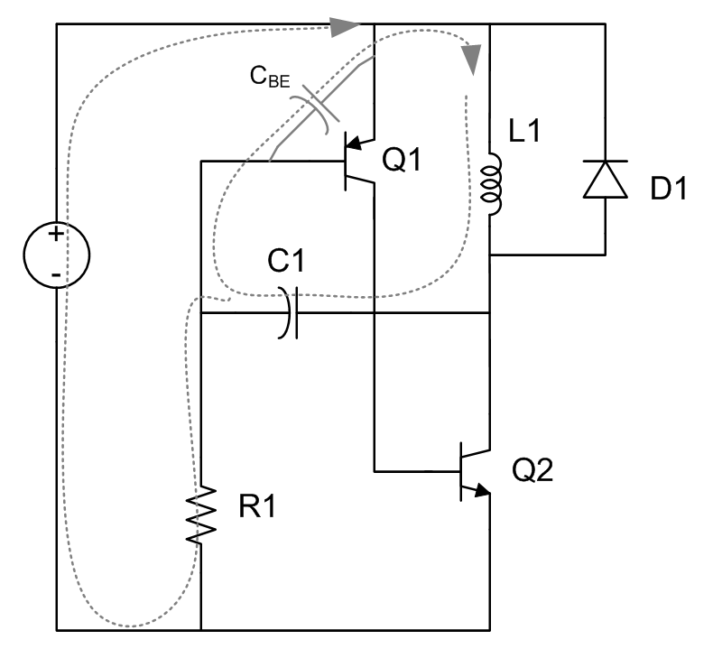
The inductor cannot completely discharge through the diode because of the diode junction voltage requirement. The inductor must finish discharging via parasitic paths in the circuit. The only path for discharge is through C1 and CBE in parallel with R1 as shown below.
The inductor discharges via the parasitic path until the base of Q1 discharges enough to turn on Q1 and repeat the cycle.
A simulation of the circuit illustrates the phases of operation.
If the RC time constant is chosen short enough, the portion of the waveform that is ringing can be eliminated.
OK…interesting circuit. Quite complicated due to the inductor. It does oscillate. But why would you build such a circuit. Well, perhaps for the LED drive. Typically, and LED may require a forward voltage of 1.8 to 2.8 volts. If you wanted to power the oscillator with a single cell, then maybe you need the inductor kick-back voltage for that.

