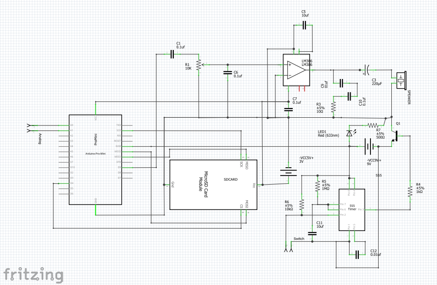
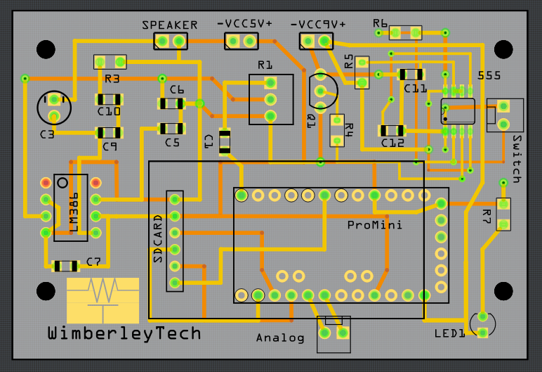
This project uses an Arduino Pro Mini, SD card reader, LM386 audio amplifier, and a 555 timer.
A list of short phrases are stored on the SD card. When a button is pushed, the Arduino powers up and randomly plays one of the stored phrases. Then it powers down. The 555 controls the timing for powering the Arduino. By using the 555, the overall system uses much less power since it is only powered for about 10 or so seconds (choosing different timing components will achieve different power-on times).
The wav file is played using the TMRpcm Arduino library. In order to play a wav file, it must have the following characteristics:
Name: maximum of 8 characters with no extension
Samples per second: 16000
Channel: Mono
Bits per sample: 8
Using Audacity, any wav file can be reformatted to these settings.
Here is an outline of the setup process. These instructions assume that the device is in default mode from factory and never been programmed.
Setup Slave device
Connect Nano to HC-05 in using AT Command setup wiring
Verify AT command response
Get address of Slave using AT command, record address value
Setup Master device
Connect Nano to HC-05 in using AT Command setup wiring
Verify AT command response
Set CMODE for communication to a single device
Bind Master to Slave using Slave address recorded above.
Setup Master and Slave devices for communication
Rewire RX and TX connections on Master and Slave
Program Master with Master program code
Program Slave with Slave program code
Write application code for Master and Slave
Detailed instructions
Setup Slave Device
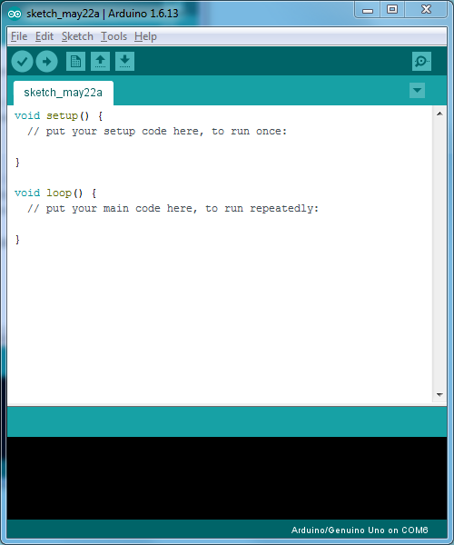
Plug the USB into the Arduino and load a blank Sketch using the keyboard shortcut: CTRL+N. It should look like Figure 1.
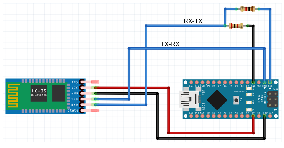
Disconnect power to the Arduino. Connect RX and TX pins as shown in Figure 1. Note that RX goes to RX (with voltage divider) and TX to TX. This is the required connection for AT command mode.
Figure 1
Physically mark the slave device with an “S” with a marker so that you will not lose track of which is the slave device. We will do the same with the master in a later step.
Figure 2
Apply power to the Arduino by plugging in the USB. The LED on the HC-05 should blink at 2-second intervals. (Some instructions tell you to press the small button on the HC-05 while applying power. However, it is not necessary if EN (Key) is hard-wired to 3.3V. The button on the HC-05 is useful, as it can be used as an alternative to hard-wiring EN (Key) pin to 3.3V. Simply leave EN (Key) pin disconnected and hold the button while powering the Arduino. )
Next, the Slave will be setup using AT commands. Open a terminal window in the Arduino environment (CTRL+SHIFT+M). Set baud rate to 38400 if it is not already. Set “Both NL and CR” at the bottom of the terminal window.
Start first AT commands by typing:
AT
The response should be “OK” or sometimes “ERROR(0)” but ignore the latter, just type AT again to get the “OK” response.
Confirm that the device being set up as a Slave, type
AT+ROLE?
The response in the terminal window should be:
+ROLE:0
This indicates “Slave” mode. If instead the device was previously setup as a Master, we would not to change ROLE to 1. Setting ROLE to 1 will be described in the Master Setup section of this tutorial.
Next get the address of this HC-05 module.
AT+ADDR?
The HC-05 will respond with a number that looks similar to this: 98d2:31:fd4ea1 This number must be recorded on paper or in a notepad on your computer. It will be needed later.
This is all that is required for the Slave module.
Unplug the Arduino.
Setup Master Device
Plug the USB into the Arduino and load a blank Sketch in the Arduino environment using the keyboard shortcut: CTRL+N. It should look like Figure 1.
Initial wiring for Master setup is the same as it was for Slave setup and is shown in Figure 2. Physically mark the slave device with a “M” with a marker so that you will not lose track of which is the slave device.
Apply power to the Arduino by plugging in the USB. The LED on the HC-05 should blink at 2-second intervals. (Some instructions tell you to press the small button on the HC-05 while applying power. However, it is not necessary if EN (Key) is hard-wired to 3.3V. The button on the HC-05 is useful, as it can be used as an alternative to hard-wiring EN (Key) pin to 3.3V. Simply leave EN (Key) pin disconnected and hold the button while powering the Arduino. )
Next, the Master will be setup using AT commands. Open a terminal window in the Arduino environment (CTRL+SHIFT+M). Set baud rate to 38400 if it is not already. Set “Both NL and CR” at the bottom of the terminal window.
Three things must be accomplished setting up the Master module
Change ROLE to Master
Change connection mode
Bind the Master to the Slave using the Slave address recorded earlier
Start first AT commands by typing:
AT
The response should be “OK” or sometimes “ERROR(0)” but ignore the latter, just type AT again to get the “OK” response.
Change the ROLE of the device to Master, type
AT+ROLE=1
The response in the terminal window should be:
OK
Verify that the change was made by typing:
AT+ROLE?
The response should be:
+ROLE:1
Next, check the connection mode:
AT+CMODE?
The device will probably return:
+CMODE:1
This means that the device can connect to any device. Change it to CMODE=0 because we want to talk to only one device.
AT+CMODE=0
The response should be “OK”
Next bind address of this HC-05 module to the Slave device using the Slave address captured earlier. However, we will replace the colons (“:”) with commas (“,”).
AT+BIND=98d2,31,fd4ea1
The HC-05 will respond with “OK”
This is all that is required for the Master module.
Setup Master and Slave devices for communication
Now that Master and Slave modules have been setup, the wiring must be changed in order for them to communicate. The wiring change is identical for Master and Slave and is described below.
Disconnect power. Remove the connection between EN (Key) and 3.3V, and switch RX and TX connections at the Arduino resulting in the circuit shown in Figure 3. Make these changes on both devices.
Power both devices. After a few moments, both devices should be blinking quick blinks in close synchronicity about every two seconds.
Figure 3
Write application code
Next, step is writing application code to send information between master and slave. Simple enough, but the HC-05 attached to the RX/TX pins impedes downloading code to the Arduino. So, in order to download code, the RX and TX pins need to be temporarily removed. After download, they may be re-attached. For a final product, a DPDT switch can be installed inline with the RX/TX pins.
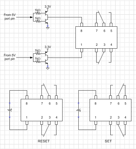
I bought some AXICOM latching relays on Ebay for cheap. They are 3V relays. Latching relays are nice because there is no holding current required to keep in one state or the other. All you have to do is drive them differentially and pulse them +/- to put it in one state and then pulse it -/+ to put it in the other state.
To use these with an Arduino Uno whose outputs I/O are 5 volt, level translation is required. There are chips that do level translation but when I wanted to set one of these up, I did not have any level-translator ICs in my lab. I have plenty of bipolar transistors, however. Using 2n3904 and 2n3906 transistors, I constructed this simple circuit. I derive the 3.3V power from the Arduino Uno board.
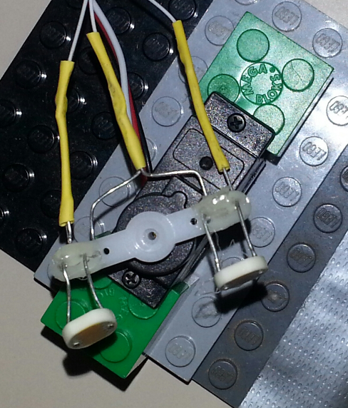
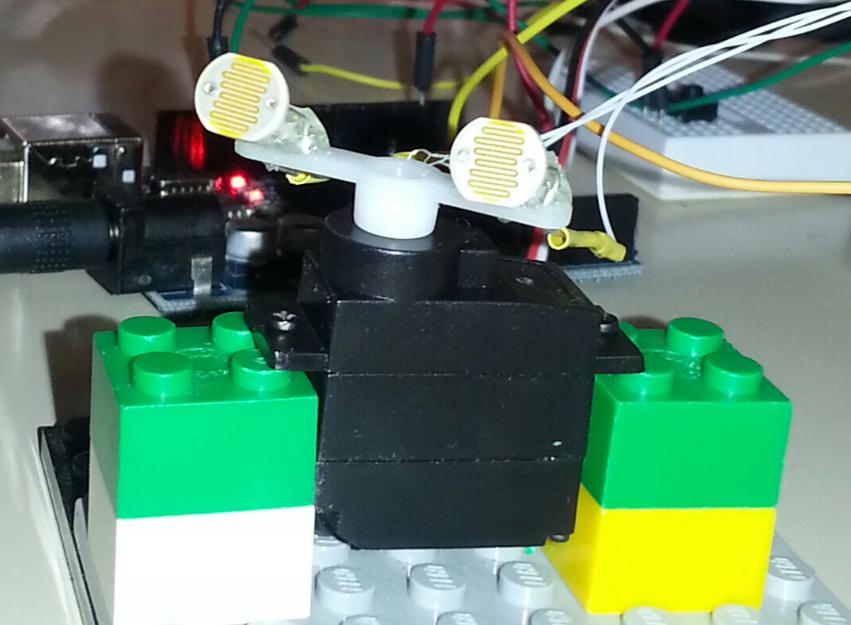
This is a simple light follower application using two CDS photocells. I included a calibration feature to account for the difference between the photocells and the resistors. Photocells are mounted as shown using hot glue. The servo is the standard one that comes with the Sparkfun Arduino inventors kit.
This coded modified by Wimberleytech LLC and placed into the public domain 31 May 2016
*/
#include <Servo.h>Servo myservo; // create servo object to control a servo
// twelve servo objects can be created on most boardsint pos = 90; // variable to store the servo position
int sensorPin0 = A0; // input from first photosensor
int sensorPin1 = A1; // input from second photosensor
const int buttonPin = 2; // the number of the pushbutton pin
int valPin0 = 0; // variable to store the value coming from the sensor Pin0
int valPin1 = 0; // variable to store the value coming from the sensor Pin1
int offset = 100;
int buttonState = 1;
int hysteresis = 5;
void setup() {
myservo.attach(9); // attaches the servo on pin 9 to the servo object
pinMode(buttonPin, INPUT_PULLUP);
Serial.begin(9600);
}
if (analogRead(sensorPin0) < analogRead(sensorPin1)-offset-hysteresis)
{
Serial.println(analogRead(sensorPin0));
Serial.println(analogRead(sensorPin1));
pos +=1;
myservo.write(pos); // tell servo to go to position in variable ‘pos’
if(pos > 160)
{
pos = 160;
}
delay(50);
}
else if (analogRead(sensorPin0) > analogRead(sensorPin1)-offset+hysteresis)
{
pos-=1;;
myservo.write(pos); // tell servo to go to position in variable ‘-pos’
if(pos < 10)
{
pos = 10;
}
delay(50);
}