I think it was Solomon who said “There is nothing new under the sun.” You may not remember Solomon, but he is the guy who wrote the lyrics to that song by “The Byrds,” “Turn Turn Turn.” Essentially, what Solomon said was that all new ideas are just old ones that have been re-entered into the race.
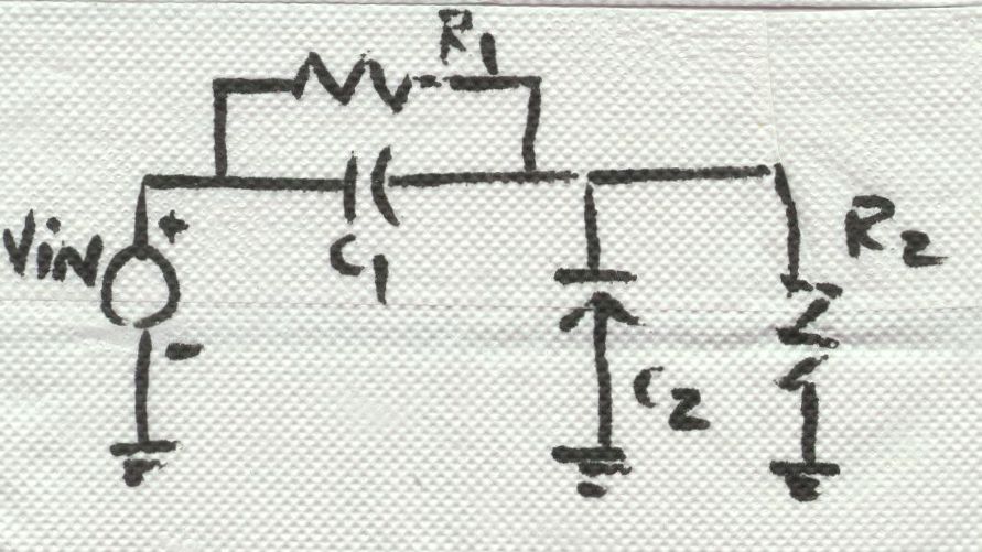
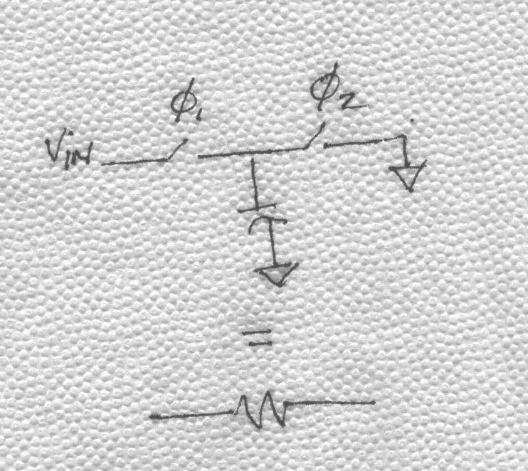
In the late 70s, in a quest to put electronic filters on integrated circuits, the genius’s at Berkeley (and elsewhere) developed the concept of the switched-capacitor filter. The idea goes something like this—you design an active filter using resistors and capacitors and then replace the resistors with a capacitor and a couple of switches so that it mimics the function of the resistor. Consider, for example, the damped integrator illustrated in BarNapkin 1.

BarNapkin 1
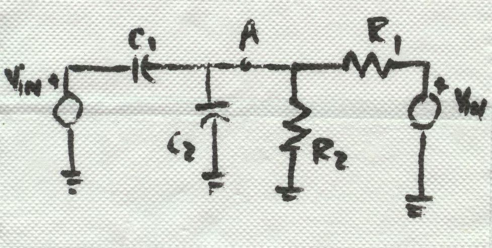
If you want a switched-capacitor implementation of the damped integrator, you substitute a switched-capacitor equivalent for each resistor. A switched-capacitor equivalent resistor is illustrated in BarNapkin 2.
BarNapkin 2
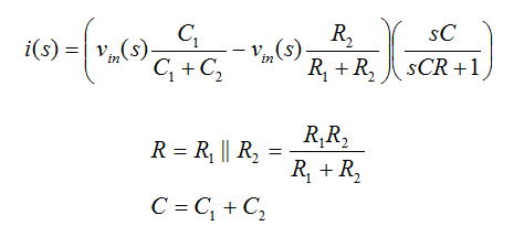
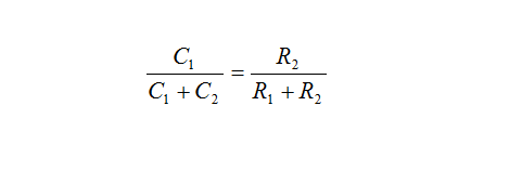
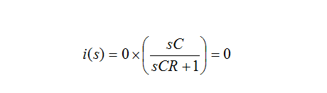
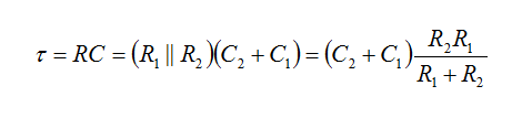
As shown, all you need is a couple of switches and a capacitor. Of course, you need to drive the switches with the appropriate clocks—it won’t work without them. Once you do the substitution, you get the circuit shown in BarNapkin 3.
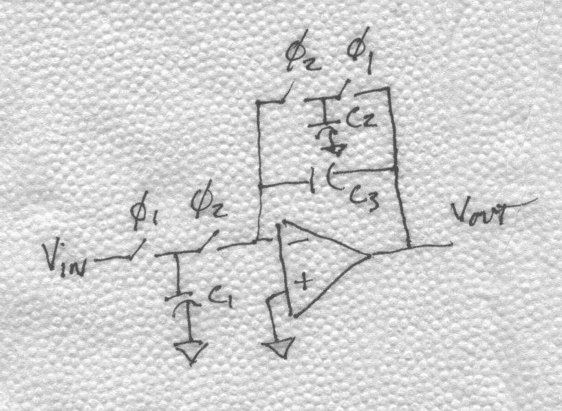
BarNapkin 3
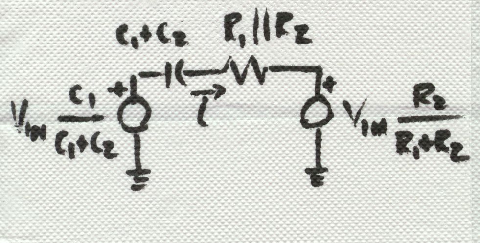
How is it that a capacitor and a couple of switches (driven by non-overlapping clocks) can act like a resistor? It is pretty simple really. Consider again, BarNapkin 2. When the switch on the left is turned on (while the one on the right is off), the capacitor is filled with charge (C times Vin). Then, when the left switch opens and the right switch turns on, the charge is dumped out of the capacitor. The time elapsed while the charge was transferred from the input to ground is simply the period of the clock, T. So the current that flows (on average) is CVin/T. Our intuition should be satisfied if we recall that current is charge per unit time (i.e., coulombs per second). If instead we were to calculate the current through a resistor, we would have found it to be Vin/R. So, it looks like the capacitor and switches mimic a resistor of value T/C! The benefits of this little bit of trickery are enormous because it allows integrated circuit designers to build filters whose accuracy depends primarily on the accuracy of clocks and capacitor ratios. Clocks can be made really accurate—in the ppm range. What about capacitor ratios?
Once those Berkeley guys (and others) developed the switched-capacitor concept, they went on to figure out how to make perfect capacitor ratios. Careers were made doing this stuff, and a few Ph.D.s to boot. After a lot of analyzing and pondering (and dissertating) they came up with some basic principals that you must apply to achieve the best possible capacitor matching. These are, 1) build all capacitors from multiples of the same unit capacitor (the unit matching principle), 2) lay out capacitors with a common centroid, 3) maximize area to perimeter ratio of the capacitor layout, and 4) match the proximity of all capacitors. If you follow these rules when you build switched-capacitor filters, you can make very robust high-performance switched-capacitor circuits.
What does all of this have to do with Solomon? Well, for one thing, the idea of emulating a resistor by switching a capacitor did not originate in the 70’s at Berkeley and elsewhere. In fact, James Clerk Maxwell had the idea in the previous century. Who knows, someone may have thought of it before him but did not write it down. As for those matching principles…?
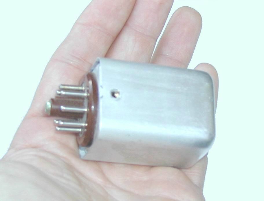
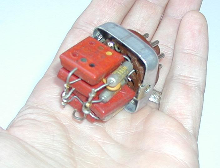
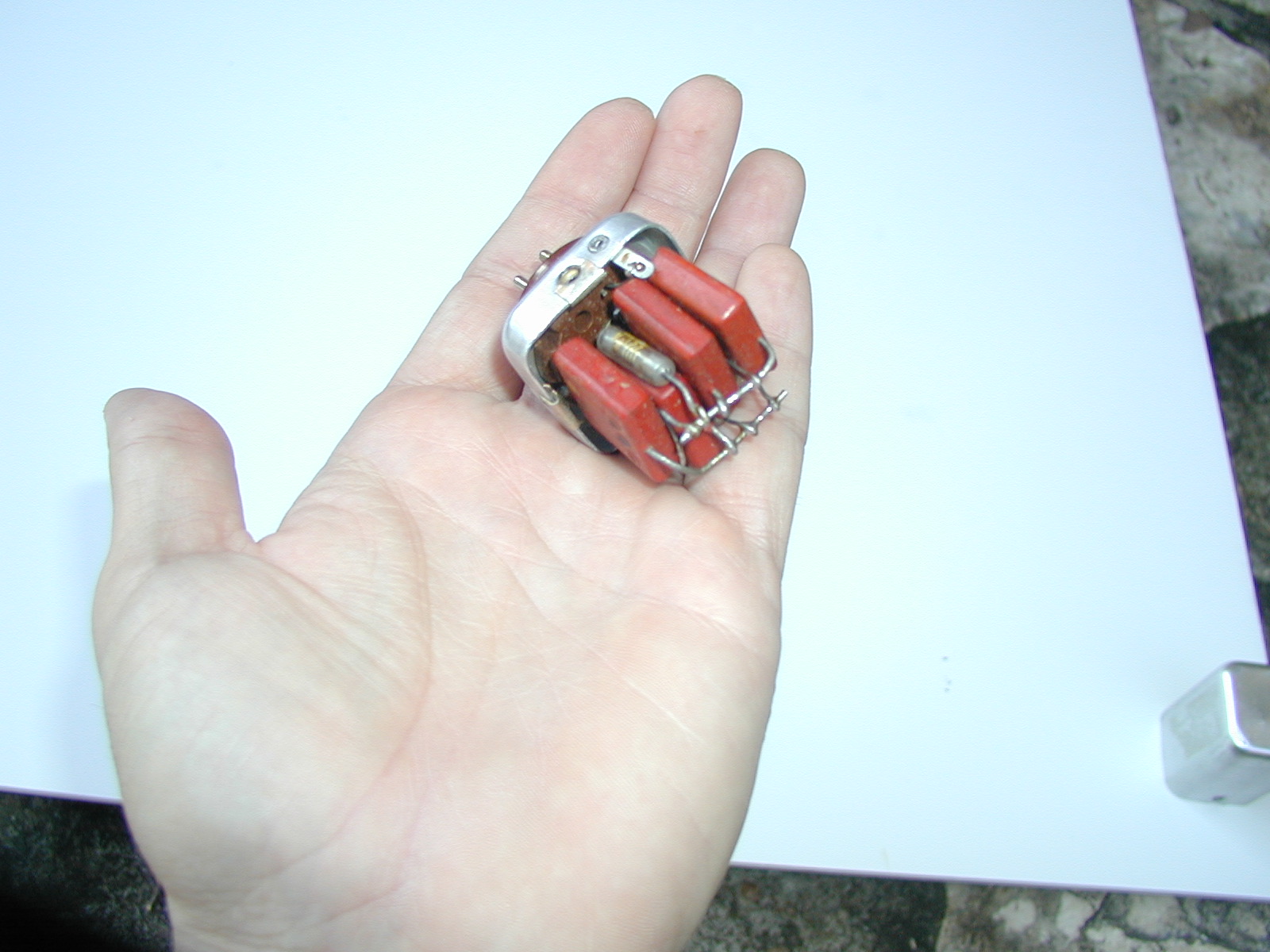
When I first moved to Austin, Texas in 1980, my buddy and I would frequent “electronic garage sales” in the area. We would buy things we never used (though we always thought we would). One of the things I picked up was a Twin-T filter mounted in a metal case with pins on the bottom that fit the footprint of a vacuum tube. Some years later, I took the thing apart to see what was inside (used to drive my parents crazy when I was a kid!). What did I find inside but a very old demonstration of the unit-matching principle! Take a look at the circuit shown in BarNapkin 4.
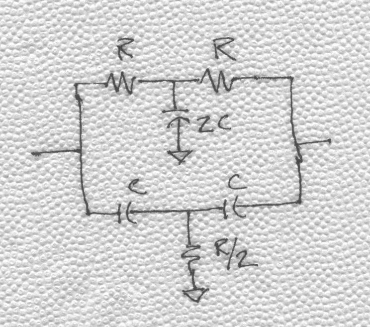
BarNapkin 4
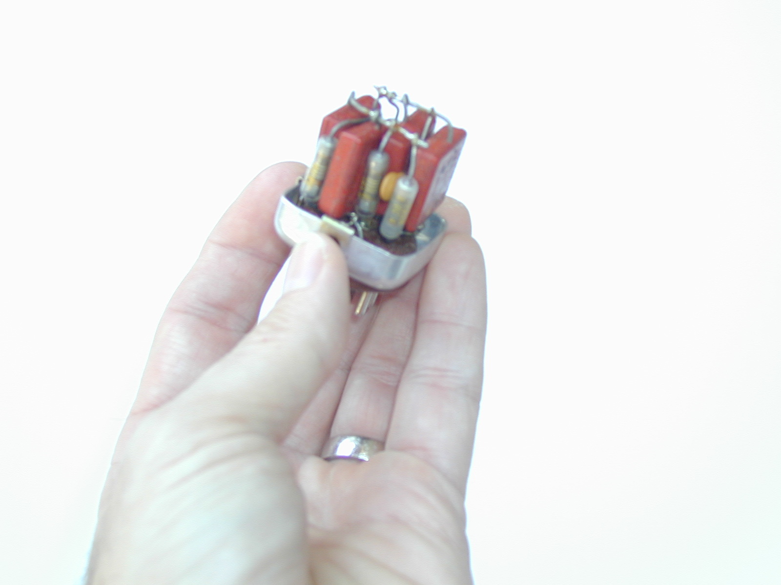
As you can see, the circuit is made up of integer units of Rs and Cs. Now look at the pictures showing the Twin-T. If you look carefully at the components you will count four capacitors and four resistors. That is what you would expect. When you make R/2, out of two Rs in parallel, and make the 2C capacitor, out of two Cs in parallel you account for two Rs and two Cs. The other two Rs and Cs are obvious from the schematic. With further close examination, you see a little disc capacitor. It is about 22 pF whereas the other capacitors are 7 nF. I suppose it is there to tweak the notch—even the unit matching principle is not perfect!
Like the switched-capacitor filter and the unit matching principle, I imagine there are other examples of older concepts reapplied in a modern context. So, I think we can trust Solomon’s wisdom, “There is nothing new under the sun.”